Topics covered in this article include:
- Introduction
- Measurement Summary
- Instructions
- Available Tests
- Image Acquisition Suggestions
- Detailed Discussion of Measurements
- Example File
Introduction
The asymmetric field measurement (also known as jaw position indicators (asymmetric)) routine measures the accuracy of field delivery using two asymmetric fields using the Standard Imaging FC-2 or Doselab RLf phantom. Measurements in the asymmetric field measurement routine include measured vs nominal field sizes and field edge positions vs nominal.
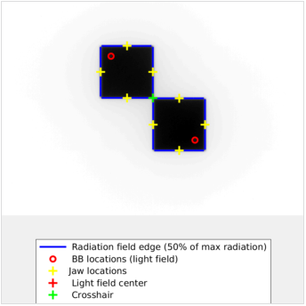
The jaw positioning is evaluated by capturing two images of a BB phantom aligned to the lasers in a collimated radiation field measured on an Electronic Portal Imaging Device (EPID) with the jaws collimating opposing quadrants in each image. The edges of the collimated fields and the BB locations are measured and compared. Ideally the bottom of the radiation field top image and the top of the radiation field bottom image would align as would the center edges of the top and bottom radiation fields.

Task Group 142 (TG-142) of the American Association of Physicists in Medicine (AAPM) recommends that the jaw position indicators (asymmetric) should be checked during monthly Quality Assurance (QA) in the Mechanical subsection of Table II.
Measurement Summary
The analysis provides the following results:
- Measured vs nominal field sizes
- Field edge positions vs nominal
- Asymmetric Jaw Gap/Overlap
The measurements are completely automated, requiring the user only to drag and drop the image set into the web-based software interface. A detailed report is created.
Instructions
If multiple sets are being uploaded, each set should have unique series instance UID DICOM tags (tag 0020,000E) to correctly break the images into sets. Below are the steps taken to process multiple image sets without unique series instance UIDs:
- If there are only two images uploaded in a group they will always be assumed to be a pair, regardless of the series instance UID DICOM tag.
- After grouping by series ID all groups with 1 image will be paired up in the order the routine sees them (an alphanumeric sort).
- If groups end up with more than two images, an attempt will be made to pair up images by the placement of the open field.
Asymmetric field test images must be DICOM files. If you have added the appropriate tests to your template, you will be able to select the test from the Type drop-down, as shown below. There are limited options for encoding the analysis into the filename, but this is not the the suggested method.
Alternatively, limited capabilities to manually identify planar images using DICOM tag values have been added to the image processing system. This is an extension of the existing naming convention system. The PatientID, StudyID, and SeriesDescription DICOM tags are checked and if the text "asym" or "asymdl" (case insensitive) is found the image set will be processed as a asymmetric field test series. For more details see Manual Identification of RT Planar Images and Individual Catphan Slices through DICOM tags.
When imaging QA tests are added to templates an upload control will appear in the scheduled QA's data entry screen allowing the user to upload images for automated analysis.
To add files to the upload queue simply drag them from a Windows Explorer folder to the drag and drop folder and release them. Alternatively, by clicking on the Add Files button to the lower right of the control a windows file selection dialog will open and files can be selected for upload. Under either method, multiple files may be selected for upload at once.
If the automatically upload checkbox is checked (the default) then file uploading will start immediately as files are added.
If the automatically upload button is turned to off the file upload process must be started manually clicking the Start upload button on the lower right of the control. To clear the upload queue click the Clear button.
Once file series have been uploaded they will be displayed below the upload control. To remove a series from the queue click the Cancel button beside the series. To start processing click the Start Processing button. A description for the image series can be added at this point. Click the Edit button next to the series. Type a description for the series into the text box that appears below Description and either click Save or press the enter key. The description can also be edited after the images have been processed. Descriptions will appear in the report with the analysis of the series.
While files are being processed users may perform other tasks such as data entry.
Available Tests
| Template Section | Subsection | Tests |
| Monthly Linac QA [TG-142 Table II] | Analysis (FC-2 Phantom) |
|
| Asymmetric Field Analysis (Doselab Radlight Phantom) |
|
Image Acquisition Suggestions
The phantom should be aligned to the light field. The software expects two images with the collimated field in opposing quadrants. The BB should not touch the edge of the radiation field.
Detailed Discussion of Measurements
Below is an example of the report generated from the asymmetric field test:
Example File
Below are example files for a asymmetric field test series for use in testing:

